English
 中文简体
中文简体 Español
 عربى
عربى
Why Valve Selection Determines Product Performance
An aerosol valve is one of the smallest components in a pressurized package, yet it controls almost every measurable outcome a formulator or brand owner cares about: spray pattern, dispensing rate, particle size, and the consistency of output from the first actuation to the last. A mismatched valve can turn a well-developed formula into an inconsistent, wasteful, or even unsafe product. Choosing correctly is not a matter of picking whatever is on hand; it requires matching orifice geometry, stem design, spring tension, and housing material to the specific viscosity, propellant ratio, and delivery goal of the product.
This guide walks through the mechanical anatomy of a standard valve, compares the two dominant mounting formats, breaks down quantitative flow behavior, and provides a practical framework for narrowing down stem and orifice choices based on real formulation variables.
Anatomy of a Standard Valve Assembly
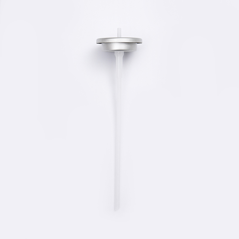
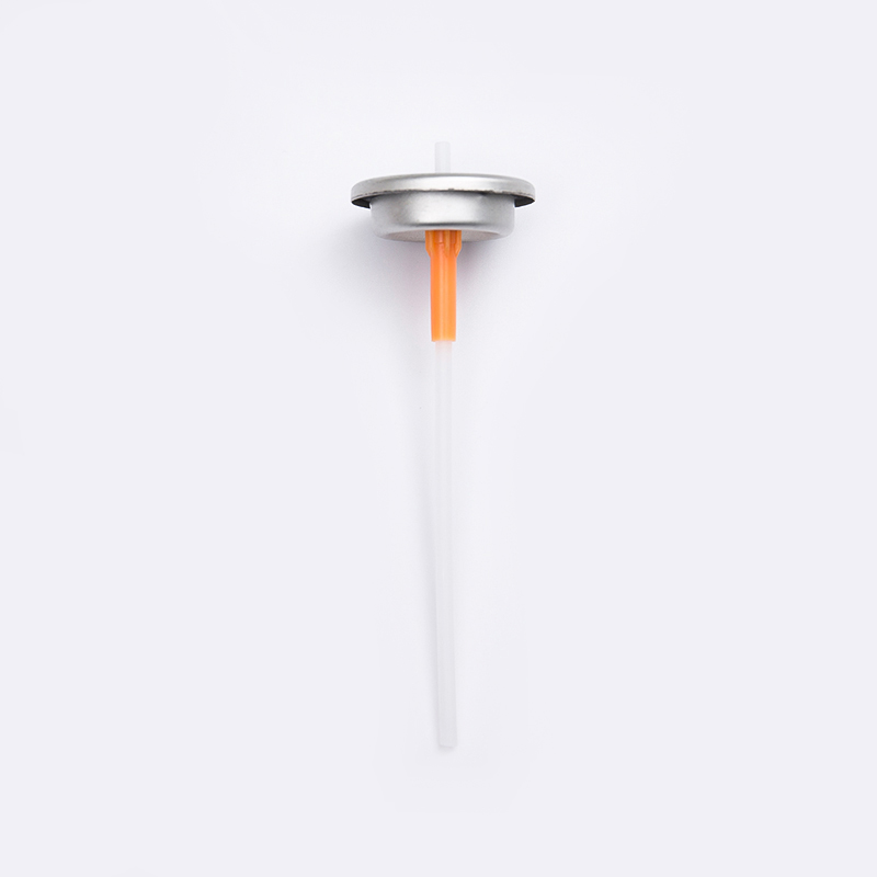
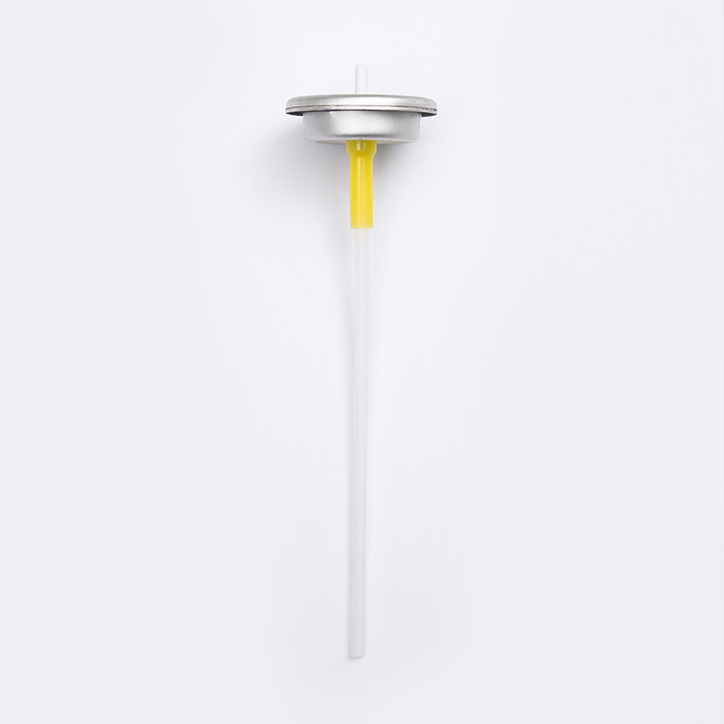
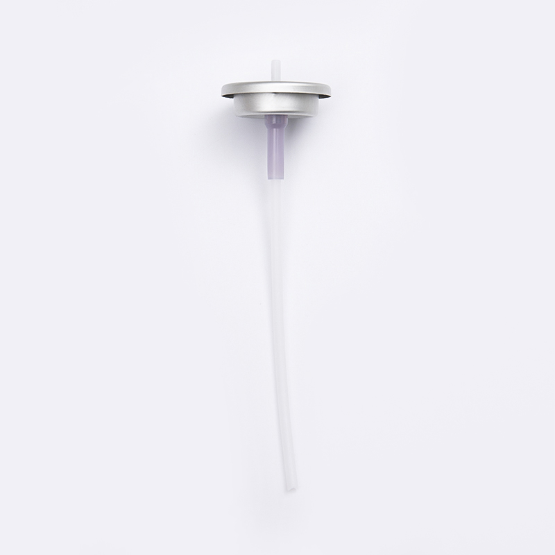
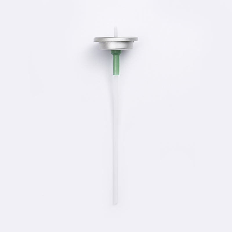
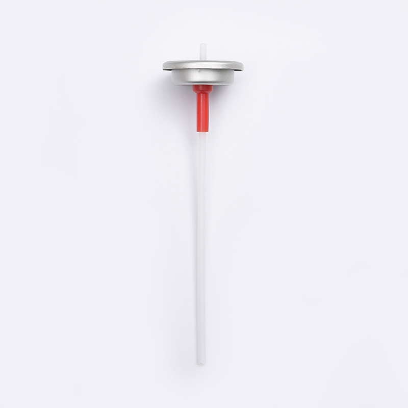
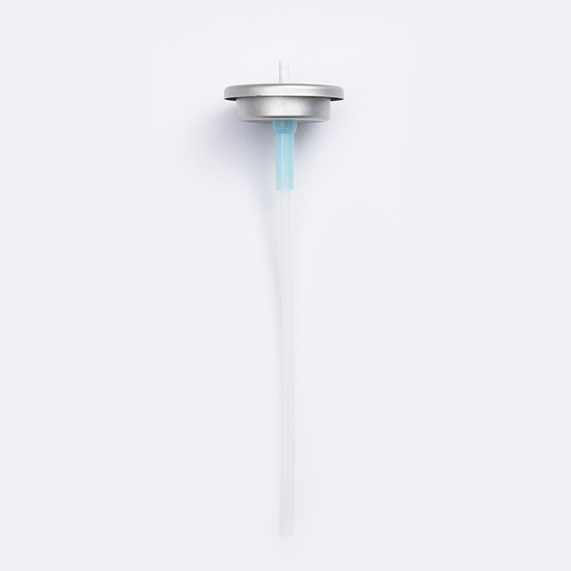
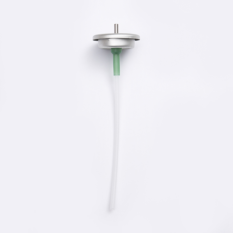
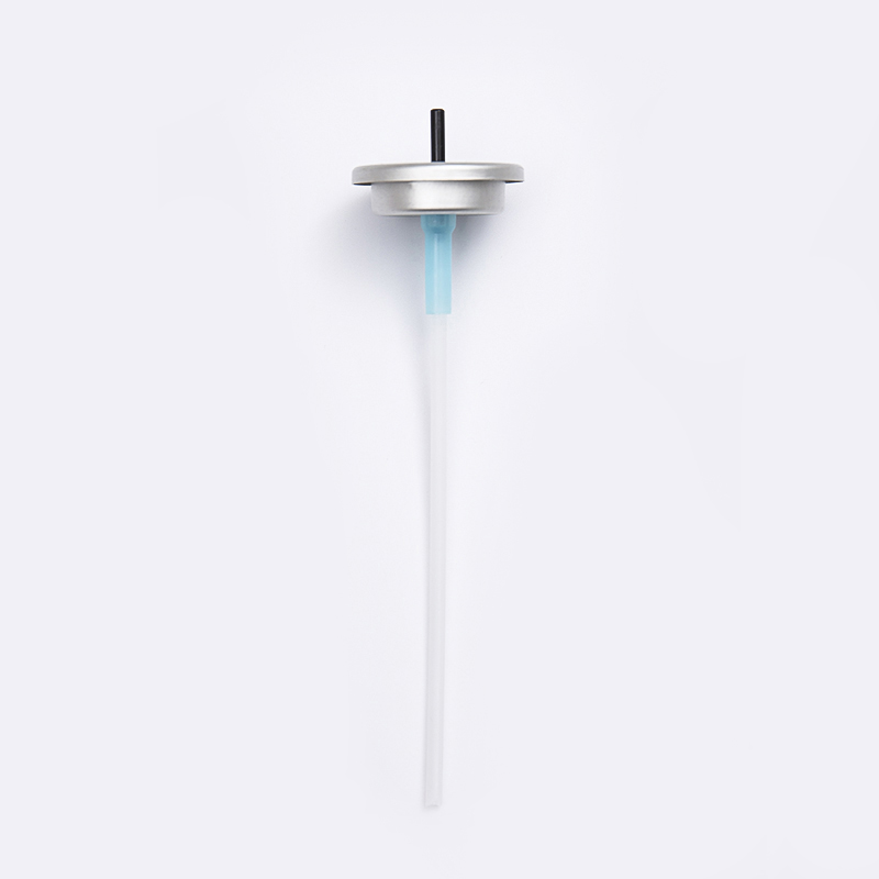
Every functional valve aerosol system, regardless of mounting style, shares a common set of internal parts. Understanding how each piece contributes to performance makes it much easier to interpret a technical data sheet.
| Component | Function | Common Materials |
|---|---|---|
| Mounting Cup | Seals valve to can, provides crimp surface | Tinplate, aluminum |
| Stem | Directs product to actuator, opens/closes flow path | Nylon, acetal, stainless steel |
| Housing | Contains spring and stem, meters intake | Nylon, polyacetal, polypropylene |
| Spring | Returns stem to closed position | Stainless steel wire |
| Gaskets | Prevent leakage at stem and cup | Buna-N, EPDM, thermoplastic elastomer |
| Dip Tube | Draws liquid from base of can to valve | Polyethylene, polypropylene |
One Inch Valve Selection vs 20mm Valve Systems
The two dominant mounting formats in the industry are the one inch (25.4mm) cup, used almost exclusively in North America, and the 20mm cup, which is the global standard across most of Europe, Asia, and Latin America. The distinction matters because tooling, crimping equipment, and replacement components are not interchangeable between formats.
| Attribute | One Inch Valve | 20mm Valve |
|---|---|---|
| Primary Region | North America | Europe, Asia, Latin America |
| Cup Diameter | 25.4 mm nominal | 20 mm nominal |
| Can Compatibility | US-standard beaded cans | Global-standard beaded cans |
| Typical Applications | Household, personal care, automotive | Personal care, food contact, technical sprays |
| Crimp Tooling | US-format crimping heads | Metric crimping heads |
Choosing the wrong cup diameter is one of the most common and costly errors in early-stage aerosol development, since it forces a full retool of filling equipment rather than a simple component swap.
Quantitative Valve Flow Rates: What the Numbers Mean
Flow rate is typically expressed in grams per second under standardized test conditions, using a reference propellant and pressure. This number reflects the combined restriction created by the vapor tap, housing orifice, stem orifice, and actuator insert working together, not any single component in isolation.
These bands are guidelines, not fixed rules. A high-viscosity gel formulation may require a wider stem orifice even in a personal care application specifically to avoid clogging, while a low-viscosity solvent-based product may need a narrower restriction to prevent over-delivery and drip. The relationship between orifice size, propellant type, and internal pressure is not linear, which is why bench testing with the actual formulation is always recommended before committing to volume production.
Technical Parameters for 20mm Valves
Within the 20mm format itself, several sub-parameters differentiate one valve from another. These are the specifications typically requested on a data sheet or purchase order.
- Vapor tap size: controls how much propellant vapor is blended into the discharge stream, directly affecting particle size and foam structure.
- Housing orifice diameter: sets the maximum intake rate from the dip tube into the metering chamber.
- Stem orifice diameter: the final restriction before the actuator, most directly tied to overall flow rate.
- Number of vapor taps: single or dual tap configurations, used to fine-tune the propellant-to-product ratio at the point of discharge.
- Dip tube length and inner diameter: matched to can height and product viscosity to avoid starvation at low fill levels.
- Gasket compound: selected for chemical compatibility with the formulation, particularly for high-alcohol or solvent-heavy products.
| Parameter | Typical Range | Primary Effect |
|---|---|---|
| Vapor Tap Diameter | 0.020 to 0.040 inch | Spray fineness, foam density |
| Housing Orifice | 0.070 to 0.150 inch | Maximum intake volume |
| Stem Orifice | 0.013 to 0.030 inch | Overall discharge rate |
| Dip Tube ID | 0.110 to 0.160 inch | Resistance to viscous product |
Selecting the Right Valve Stem for Aerosols
The stem is the component most directly responsible for actuator compatibility and discharge consistency, so it deserves particular attention during selection.
- Match orifice to viscosity: thicker formulations need a proportionally larger stem orifice to avoid inconsistent or sputtering discharge.
- Confirm actuator fit: stem outer diameter and shoulder design must correspond exactly to the actuator's inner bore, or leakage and wobble will occur.
- Check chemical compatibility: solvent-heavy or high-alcohol formulas can swell or degrade certain plastics over shelf life, so material choice should be validated against the actual formula, not a generic reference.
- Consider tilt versus vertical actuation: some stem designs are built specifically for tilt-action dispensing, while others are optimized for straight vertical actuation only.
- Account for spring force: a heavier spring gives a firmer, more controlled actuation feel but requires more finger pressure, which matters for accessibility and user experience.
For a valve aerosol assembly intended for continuous or high-frequency use, stem wear resistance becomes as important as initial flow rate, since repeated actuation cycles can gradually enlarge the orifice in lower-grade plastics and shift the spray pattern over the life of the can.
Matching Valve Design to Formulation and Delivery Goal
Rather than selecting a valve first and adjusting the formula around it, the more reliable workflow starts with the delivery goal and works backward into component specification.
Low-viscosity, alcohol-based products generally pair well with narrow stem orifices and single vapor taps, producing a fine, dry mist. Water-based lotions and creams typically need wider orifices and larger housing intake to prevent starvation, since thicker product resists flow through the dip tube. Foaming products rely heavily on vapor tap configuration and often use dual-tap housings to blend propellant more thoroughly into the stream before discharge. Products with suspended particulates, such as certain cleaning sprays, need larger internal clearances throughout the entire valve to avoid clogging over the shelf life of the can.
Common Failure Modes and How Testing Prevents Them
Most field complaints about aerosol products trace back to one of a small number of valve-related root causes. Identifying these early during development testing avoids costly recalls or reformulation later.
| Symptom | Likely Cause | Typical Fix |
|---|---|---|
| Weak or inconsistent spray | Undersized stem orifice for viscosity | Increase stem orifice diameter |
| Excessive dripping after use | Oversized orifice or worn stem seal | Reduce orifice size, upgrade gasket |
| Product does not discharge near empty | Dip tube too long or too rigid | Shorten or adjust dip tube length |
| Leakage around stem | Incompatible gasket material | Switch to chemically resistant compound |
| Sputtering, uneven spray pattern | Vapor tap sized incorrectly for propellant ratio | Adjust vapor tap diameter or count |
Standard validation should include actuation cycle testing across the full expected shelf life, drop testing under pressure, and delivery rate testing at both full and near-empty fill levels, since flow characteristics can shift meaningfully as internal pressure drops toward the end of a can's life.
Practical Selection Checklist
Before finalizing a valve specification, confirm the following points against the actual formulation and packaging line.
- Cup diameter matches the can format and regional filling equipment already in use.
- Stem orifice and housing orifice are validated against actual formula viscosity, not a generic reference product.
- Gasket material has been checked for long-term chemical compatibility with the formula.
- Vapor tap configuration matches the intended spray character, whether fine mist, foam, or stream.
- Dip tube length is correct for the can height and expected fill volume.
- Flow rate has been bench tested at both full and near-empty fill conditions.
- Actuator bore and stem outer diameter are confirmed to be a precise mechanical match.
Frequently Asked Questions
Q1: What is the difference between a one inch valve and a 20mm valve?
The difference is primarily the cup diameter and regional standard. One inch valves use a 25.4mm cup common in North America, while 20mm valves use a smaller metric cup that is the standard across most other global markets. The two are not interchangeable without matching crimping tooling.
Q2: How is aerosol spray valve flow rate actually measured?
Flow rate is measured in grams discharged per second under a standardized test using a reference propellant and pressure. It reflects the combined restriction of the vapor tap, housing orifice, and stem orifice, so changing any one component will shift the measured rate.
Q3: Can the same valve be used across different formulations?
Sometimes, but it is risky to assume compatibility without testing. Viscosity, propellant ratio, and chemical compatibility with gasket materials can all differ enough between formulas to require a different stem orifice or gasket compound, even within the same product category.
Q4: Why does spray performance change as a can empties?
As product is discharged, internal can pressure gradually decreases, which can reduce flow rate and alter spray pattern, particularly in formulations that rely heavily on propellant vapor for atomization. This is why near-empty testing is a standard part of valve validation.
Q5: What causes an aerosol can valve to leak?
Leakage is most often caused by a worn or chemically incompatible gasket, an improperly seated stem, or a cup crimp that was not sealed correctly during filling. Chemical compatibility testing during development significantly reduces this risk over the product's shelf life.