 English
 中文简体
中文简体 Español
 عربى
عربى
Not every spray aerosol valve is built for every propellant. The internal pressure dynamics of a liquefied gas behave entirely differently from those of a compressed gas, and these differences ripple through every component selection decision — from gasket elastomer to valve stem diameter to orifice sizing. Getting this match wrong leads to seal degradation, inconsistent spray output, and premature product failure. Getting it right means a product that performs consistently across its entire shelf life.
This guide breaks down the technical considerations that determine valve-propellant compatibility, covering the two major propellant classes, key valve subcomponents, and the specification parameters that matter most for each use case.
The Two Propellant Classes and How They Behave
Every aerosol propellant system falls into one of two fundamental categories: liquefied gas propellants or compressed gas propellants. These categories are not interchangeable, and the mechanical behavior of each places different demands on valve design.
Liquefied Gas Propellants
Liquefied gas propellants exist in a two-phase equilibrium inside the container — part liquid, part vapor. As product is dispensed and pressure drops momentarily, additional liquid vaporizes to restore pressure. This self-regulating behavior means the can delivers relatively consistent pressure throughout most of its service life, declining only near the end when liquid propellant is nearly exhausted.
Common examples include hydrocarbons such as propane, n-butane, and isobutane, as well as hydrofluorocarbons (HFCs) and dimethyl ether (DME). Isobutane operates at approximately 3.1 bar at 20 degrees Celsius, while propane sits closer to 8.4 bar under the same conditions.
Compressed Gas Propellants
Compressed gas propellants — primarily nitrogen, carbon dioxide, and nitrous oxide — are stored entirely in the gas phase. There is no liquid phase present. Container pressure drops in a nearly linear relationship with the amount of product dispensed: a half-empty can has roughly half the original headspace pressure. Spray force and particle size shift noticeably over the product's life unless the formulation or valve is specifically engineered to compensate.
Compressed gases operate at substantially higher initial pressures than most liquefied systems. Nitrogen-pressurized cans may be filled to 8–12 bar at room temperature, which demands valve components — gaskets, stems, and housing — rated for extended exposure to those pressures without creep or extrusion failure.
- Two-phase: liquid + vapor
- Self-regulating pressure
- Consistent spray output over life
- Typical range: 2 – 8 bar at 20 °C
- Requires solvent-resistant gaskets
- Examples: butane, isobutane, DME, HFCs
- Single-phase: gas only
- Pressure declines with use
- Spray force decreases over time
- Typical range: 6 – 12 bar at fill
- Requires high-pressure creep resistance
- Examples: N2, CO2, N2O
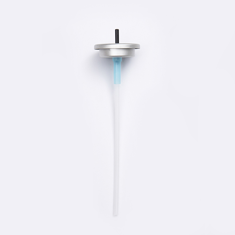
Aerosol Valve Anatomy: Components That Determine Compatibility
An aerosol valve assembly consists of several discrete components, each of which must be independently evaluated for compatibility with the chosen propellant and concentrate. Understanding what each part does clarifies why compatibility decisions are made at the component level rather than the assembly level.
The Valve Stem
The valve stem is the central moving element. When actuated, it shifts downward, aligning internal channels and allowing pressurized product to travel from the container through the stem orifice to the actuator nozzle. The 2.80 Valve Stem (available in both plastic and metal configurations) is one of the industry's most widely specified stem diameters, offering a balance between flow rate control and structural strength under pressure.
Stem material selection hinges on two factors: chemical compatibility with the concentrate and propellant, and mechanical performance at operating pressure. Metal stems are generally preferred when aggressive organic solvents are present, while plastic stems offer adequate performance in water-based and lower-solvent formulations.
The Valve Core: Understanding the 4.60 Series
The 4.60 Valve Core Series (plastic) refers to a family of inserts that determine the metered dose or continuous-flow orifice dimensions. The 4.60 designation refers to the nominal outer diameter of the core insert in millimeters, which must seat precisely within the valve housing to prevent bypass leakage and ensure repeatability.
For metered-dose applications — personal care, pharmaceutical aerosols, certain industrial lubricants — the valve core's orifice geometry directly determines the volume dispensed per actuation. Tolerances of plus or minus 0.05 mm on the orifice can translate to dose variation of several percent, which is clinically or functionally significant depending on the application.
The Gasket System
No single component is more propellant-sensitive than the gasket. Elastomer gaskets seated at the stem interface must resist compression set (permanent deformation under sustained load), chemical swell, and extraction of plasticizers by the propellant or concentrate.
The Valve Housing
The housing encloses and supports all other components. For standard aerosol applications, housing materials are most commonly acetal copolymer (POM), nylon, or polypropylene — each with specific solvent and chemical resistance profiles. Metal housings are employed for extreme-pressure or aggressive-solvent applications where plastic housings would risk stress cracking or solvent absorption.
Gasket Material Selection by Propellant Type
Gasket elastomer compatibility is the most critical variable in aerosol valve specification. The wrong material will swell, harden, crack, or dissolve in contact with certain propellants, compromising seal integrity and leading to field failures. The table below provides a practical reference for initial material selection.
| Propellant / Concentrate Type | Recommended Elastomer | Key Property | Typical Application |
|---|---|---|---|
| Hydrocarbon LPG: butane, isobutane, propane | Buna-N (NBR) | Excellent hydrocarbon resistance, low swell | Hair spray, deodorant, insecticide |
| Dimethyl Ether (DME) | EPDM or Neoprene | DME resistance; NBR degrades in DME | Water-based aerosols, household cleaners |
| HFC (HFC-134a, HFC-152a) | Neoprene, EPDM | Fluorocarbon inertness | Medical MDIs, specialty coatings |
| Compressed Nitrogen (N2) | EPDM, Silicone | Pressure creep resistance, inert gas compatibility | Food-grade dispensers, pharma |
| Carbon Dioxide (CO2) | EPDM | CO2 gas permeation resistance | Beverage dispensing, industrial |
| Nitrous Oxide (N2O) | EPDM, Silicone | Oxidizer compatibility, no degradation | Food whipping cream, specialty |
| High-solvent concentrate + hydrocarbon | Buna-N, high-density grade | Dual resistance: solvent + hydrocarbon | Industrial lubricants, paints |
This table reflects general guidance; actual compatibility should always be validated with immersion testing in the specific formulation across the intended use temperature range.
Valve Component Specification: Matching Parts to Propellant Systems
Selecting individual valve components requires evaluating several parameters in combination. No single specification works across all propellant and concentrate systems.
Stem Diameter and Flow Rate Considerations
The 2.80 mm valve stem is a near-universal standard for continuous-spray personal care and household product categories. This diameter, combined with a stem orifice in the range of 0.30–0.50 mm, delivers flow rates suitable for most hair care, body spray, and general household aerosol applications using hydrocarbon propellants.
For compressed gas systems — where upstream pressure is higher initially but drops significantly over product life — a slightly larger stem orifice may be specified to ensure adequate flow at end-of-life pressure conditions, compensating for the absence of self-regulating vapor pressure behavior.
Orifice Sizing for Liquefied vs. Compressed Propellants
Because liquefied gas systems maintain relatively constant pressure throughout most of the can's service life, orifice sizing can be optimized around a narrow target pressure window. Compressed gas systems demand a wider tolerance on acceptable flow rate, since day-one and day-last performance will differ materially. In practice, compressed-gas valve assemblies use somewhat larger orifice sizes (0.40–0.60 mm in some configurations) and may incorporate actuator designs with a wider acceptance range for variable spray geometry.
Valve Core (4.60 Series) Selection Criteria
Within the 4.60 Valve Core Series, selection variables include the inlet orifice, metering chamber volume (for metered-dose designs), and the outlet orifice. Higher-pressure compressed gas applications may require cores produced from engineering-grade polymers with tighter mold tolerances to prevent creep deformation at sustained pressures. Standard-grade cores that function correctly at 3.5 bar in a butane system may develop dimensional drift over months of service in an 8–10 bar nitrogen system.
Valve Design in Real-World Aerosol Applications
The principles described above translate directly into specification decisions across a wide range of aerosol product categories. A hair spray using an isobutane/propane blend requires a fundamentally different valve assembly than a food-grade nitrogen-pressurized cream dispenser — even though both are nominally aerosol valves.
Personal Care Aerosols (LPG Propellant)
Hair sprays, deodorants, and body sprays typically use isobutane or a propane/isobutane blend at 2.5–4.5 bar. These applications almost universally use plastic valve components — 2.80 plastic stems, 4.60 series plastic cores — with NBR gaskets. The relatively benign solvent environment and moderate pressures create no barrier to full plastic construction, keeping unit cost competitive for high-volume consumer goods.
Industrial Maintenance and Lubrication Sprays
Penetrating oils, release agents, and corrosion inhibitors frequently combine hydrocarbon propellants with concentrated aromatic or petroleum solvent bases. These formulations can attack acetal and nylon components, causing swelling that reduces flow or compromises seal geometry. Metal stems combined with solvent-grade Buna-N gaskets are the standard response in this category.
Pharmaceutical and Food-Grade Aerosols
Medical inhalers and food-grade dispensing systems face the strictest regulatory scrutiny. Valve components must be validated for extractables and leachables — the suite of compounds that could migrate from valve materials into the product under real storage conditions. These applications often require metal stems, pharmaceutical-grade EPDM gaskets, and formal compatibility studies conducted over accelerated aging periods of 6–24 months.
Environmentally Driven Reformulations
As regulatory bodies have continued tightening restrictions on HFC propellants based on global warming potential, formulation teams have moved toward compressed CO2, N2, and compressed air solutions. This shift demands a corresponding update in valve specification — particularly gaskets and stem materials — because compressed gas propellants interact with valve components differently than the liquefied gas systems they replace. Teams that carry over valve assemblies from legacy products without revalidation frequently encounter seal failure or inconsistent dose delivery.
Compatibility Validation: Testing Protocols for Propellant-Valve Pairing
Selecting components based on general compatibility guidance is the starting point, not the endpoint. All aerosol valve assemblies should be validated against the actual formulation and propellant under conditions that represent real-world storage and use scenarios.
Gasket and stem samples are submerged in the propellant-concentrate mixture at 20, 40, and 50 degrees Celsius for 7, 28, and 90 days. Weight gain exceeding 5 percent in a gasket elastomer typically signals problematic swell that will compromise seal force and flow geometry.
Complete valve assemblies are crimped onto filled cans and stored at 40–50 degrees Celsius to simulate accelerated aging. Leak testing at 1, 3, 6, and 12 months verifies seal integrity over time.
Particle size distribution, spray angle, and mass output per actuation are measured at the start of can life and at intervals, documenting consistency — particularly for compressed gas systems where pressure decline is expected.
Immersion data, leak results, and spray performance data are compiled into a compatibility dossier supporting regulatory submissions and supply chain audits.
Propellant Trends and Their Implications for Valve Specification
The aerosol industry's propellant landscape is actively shifting under pressure from environmental regulation, supply chain dynamics, and evolving consumer product categories. Each shift carries direct implications for valve component selection.
Dimethyl Ether Growth
DME has grown as a partial or full replacement for hydrocarbons in water-based aerosol products. Its miscibility with water is an advantage; its aggressive behavior toward NBR gaskets is a challenge. Products migrating from hydrocarbon to DME must revalidate gasket selection — substituting EPDM or neoprene for NBR in most cases — but this must be formally confirmed rather than assumed.
Compressed Gas Adoption in Water-Based Systems
Nitrogen and CO2 have gained traction in water-based systems — cleaning products, food sprays, personal care — as brands seek to lower volatile organic compound (VOC) content. Compressed gas systems also require attention to dip tube selection: the absence of propellant in the liquid phase means product viscosity alone governs flow into the dip tube, making dip tube inner diameter a more significant flow-limiting variable.
Lower-GWP HFO Propellants
Hydrofluoroolefins (HFOs), particularly HFO-1234ze and HFO-1234yf, are entering aerosol use as lower-GWP alternatives to HFCs. Current data suggests EPDM and certain fluoroelastomers perform well with these propellants, while NBR shows varying results. Valve engineers working with HFO propellants should prioritize direct compatibility testing over extrapolation from legacy HFC data.
Practical Specification Checklist for Valve-Propellant Matching
The following checklist consolidates the specification considerations covered in this guide. It is designed to support engineering teams during the valve selection phase of a new product development or reformulation project. To review a specific aerosol valve configuration for your application, component-level data sheets from your valve supplier are an essential starting resource.
- Identify whether the propellant is a liquefied gas or compressed gas system.
- Establish the fill pressure at maximum expected storage temperature (typically 50 degrees Celsius).
- Identify all chemical classes present in the concentrate: hydrocarbons, esters, ketones, alcohols, water, silicones.
- Select gasket elastomer based on both propellant and concentrate compatibility — the combination matters, not just the propellant alone.
- Determine whether plastic or metal stems and cores are appropriate based on solvent content and operating pressure.
- Size orifices to meet target flow rate at the expected pressure range — account for pressure decline if using compressed gas.
- Select dip tube material and diameter appropriate to concentrate viscosity and tube length.
- Conduct component immersion testing in the actual formulation-propellant mixture.
- Run filled-can stability testing at 40–50 degrees Celsius for a minimum of 3 months before commercial release.
- Document all compatibility findings in a formal dossier to support regulatory submissions and supply chain audits.
Frequently Asked Questions
Q1: What is the main difference between a valve designed for liquefied gas propellants and one for compressed gas propellants?
The core difference lies in operating pressure behavior and gasket requirements. Liquefied gas systems maintain relatively stable pressure through most of the can's life, allowing precise orifice optimization and permitting NBR or neoprene gaskets in hydrocarbon systems. Compressed gas systems have higher initial pressure that declines linearly, requiring gaskets with excellent creep resistance such as EPDM or silicone, and often slightly larger orifice dimensions to maintain acceptable spray performance as pressure drops over time.
Q2: Why is the 4.60 Valve Core Series designated by a number — what does it refer to?
The 4.60 designation refers to the nominal outer diameter of the core insert, measured in millimeters. This dimension governs the fit of the core within the valve housing and is a standardized reference used across the aerosol industry to ensure interchangeability and dimensional consistency. Different orifice configurations and metering chamber volumes are available within the same 4.60 outer diameter family, allowing performance customization without changing housing tooling.
Q3: Can a valve with a Buna-N gasket be used with dimethyl ether (DME) propellant?
This is generally not recommended. NBR (Buna-N) gaskets are known to swell and degrade in the presence of DME. Products using DME as a propellant should use EPDM or neoprene gaskets, which demonstrate substantially better dimensional stability in DME contact. If a legacy product with NBR gaskets is being reformulated to include DME, gasket revalidation is mandatory — immersion testing in the DME-containing formulation must be completed before commercial transition.
Q4: When should a 2.80 plastic stem be upgraded to a metal stem?
Both stems share the same 2.80 mm nominal diameter. The plastic version is suitable for water-based and moderate-solvent formulations at standard aerosol pressures. The metal version is required when aggressive solvents such as esters, aromatic hydrocarbons, or ketones are present in the concentrate; when operating pressure exceeds the plastic's creep resistance threshold; or when regulatory requirements mandate non-extractable materials. Metal stems add cost and weight but are the appropriate choice in demanding formulation environments.
Q5: How long should immersion testing be conducted before approving a gasket material for a new propellant?
Industry practice calls for a minimum of 28-day immersion at the highest expected service temperature (50 degrees Celsius), with 90-day data considered more definitive for long-shelf-life products. Weight gain, dimensional change, and hardness change are all measured. For pharmaceutical and food-contact applications, regulatory frameworks may require 6–24 months of filled-can stability data under accelerated conditions before a compatibility claim can be formally supported.
Q6: Are aerosol valves tested for temperature extremes, and why does this matter for propellant compatibility?
Yes. Aerosol products may experience temperatures ranging from minus 10 degrees Celsius (cold-chain or outdoor winter storage) to 50 degrees Celsius or higher (vehicles in summer, tropical shipping containers). Low temperatures can stiffen gasket elastomers and reduce seal force, while high temperatures increase container pressure in liquefied gas systems and accelerate any chemical interaction between the propellant and valve materials. Specification decisions should always reference performance across the full intended storage temperature range, not just ambient conditions.


