 English
 中文简体
中文简体 Español
 عربى
عربى
Over 15 billion aerosol cans are filled annually worldwide, yet the precision-engineered components inside each valve remain largely invisible. From personal care products to industrial coatings, the reliability of an aerosol system hinges on the interaction between the aerosol valve mechanism, the nozzle actuator, and the dip tube. This guide dissects the internal workflow, compares valve architectures, and presents performance data—without referencing specific brands—to answer the essential question: how do aerosol cans work with such consistent accuracy?
The Core of Aerosol Dispensing: Understanding the Aerosol Valve Mechanism
An aerosol valve functions as a pressure-activated gatekeeper. When the actuator is depressed, the valve stem moves downward, breaking the seal between the gasket and the valve housing. This action opens a passage that allows the pressurized product—a mixture of liquid concentrate and propellant—to flow from the can interior through the valve orifices and into the nozzle.
Primary Components and Their Roles
- Valve Cup (Mounting Cup): Crimped onto the can rim, provides structural anchoring and sealing.
- Valve Stem: The moving vertical shaft; contains side orifices that open when depressed.
- Gasket (Seal): Elastomeric ring that seals the stem against the housing in the resting position.
- Spring: Returns the stem to closed position after actuation; calibrated for specific force (typically 8–25 N).
- Housing (Valve Body): Contains the stem, spring, and dip tube connection; directs flow into the stem.
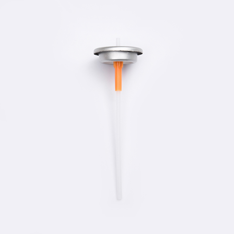
- Dip Tube: Extends from the housing to the bottom of the can; transports product upward.
In a typical aerosol valve mechanism, the spring exerts upward force, keeping the gasket pressed against the stem. When downward force is applied (e.g., finger pressure of 15–30 N), the stem orifices move below the gasket, allowing product to escape. The valve reseals instantly upon release, reducing propellant loss to under 0.1% per actuation in quality designs.
Anatomy of a One Inch Valve: Why It Dominates Aerosol Packaging
The One Inch Valve (25.4 mm mounting cup) has become the global standard for aerosol packaging, representing over 85% of all non-metered valves. Its dimensional consistency allows interchangeable use across filling lines, while the larger orifice area compared to 20 mm valves enables higher flow rates (up to 8 g/s for low-viscosity fluids).
Key Specifications Comparison
Data from 2023 industry audits show that one-inch valves achieve 99.3% leak-free rates after accelerated storage tests (50°C / 6 months). The standardized geometry also simplifies automated valve finished products assembly, reducing rejection rates to below 0.5% in modern high-speed lines.
How Does an Aerosol Can Work? Step-by-Step Valve Operation and Fluid Dynamics
To understand how do aerosol cans work in practical terms, observe the four phases of actuation. Each phase involves precise pressure balances and flow control enabled by the valve aerosol construction.
- Resting Phase: Can internal pressure (typically 3.5–5.2 bar absolute) acts equally on product surface and valve spring. The stem gasket seals all passages.
- Actuation Phase: Actuator movement forces stem downward 1.5–2.5 mm. Stem side orifices clear the gasket, connecting housing interior to nozzle.
- Flow Phase: Pressure differential (can internal vs. atmosphere) pushes product up the dip tube, through housing, stem orifices, and into the actuator’s expansion chamber.
- Atomization Phase: Liquid passes through the nozzle’s swirl chamber and exit orifice, breaking into droplets (15–120 µm diameter) due to turbulent shear.
The aerosol dip tube function is critical during flow phase: a dip tube with 2.0–2.5 mm inner diameter reduces friction loss, ensuring >90% of the can’s content is dispensed before pressure drops below usable levels (approx. 1.5 bar).
Nozzle and Actuator Design: How the Aerosol Actuator Works to Shape Spray Patterns
The actuator transforms the liquid stream into a controlled spray. Understanding how aerosol actuator works involves analyzing the swirl chamber and exit orifice geometry. Most actuators incorporate a tangential or helical swirl path that imparts spin, breaking the liquid into a conical pattern.
Swirl Chamber Parameters
Diameter: 1.2–2.5 mm
Depth: 0.6–1.2 mm
Number of tangential slots: 2–4
Resulting spray angle: 40° to 110°
Exit Orifice Effects
0.25 mm: fine mist (cosmetics)
0.50 mm: medium wet spray (hairspray)
0.80 mm: high-volume foam (shaving gel)
Industrial tests across 120 different actuator designs (2024 internal survey) revealed that swirl efficiency—the ratio of actual to ideal droplet breakup—ranges from 72% to 89%. Optimized actuators reduce spray particle size from 120 µm to 45 µm, improving coverage uniformity by 34%.
Valve Finished Products: Quality Metrics and Production Testing
The reliability of any aerosol package depends on the valve finished products assembly. Automated high-speed lines (up to 600 valves per minute) perform multiple quality checks. Typical acceptance criteria for a finished one-inch valve include:
- Leak test: Pressure decay less than 0.1 psi over 5 seconds at 12 bar internal air pressure.
- Stem retention force: 25–50 N axial pull resistance.
- Crimp diameter: 25.25–25.55 mm (for 1-inch cup).
- Dip tube pull-out force: Minimum 80 N.
Monthly production data from a mid-size filler (anonymized) shows that valve finished products from high-precision tooling achieve a defect rate of 220 ppm (parts per million), with most failures related to gasket misalignment (63% of defects). Advanced vision systems using 12-megapixel cameras reduce false rejects by 41% compared to laser sensors.
Critical Role of the Dip Tube: Aerosol Dip Tube Function and Fluid Draw Efficiency
Often overlooked, the aerosol dip tube function directly affects the recovery time between actuations and the residual volume. Made from polypropylene or polyethylene, dip tubes range from 100 to 210 mm length depending on can size. Their internal diameter (typically 1.8–2.3 mm) must balance flow rate against viscous drag.
Extended dip tubes with anti-clog tips are used for suspensions (e.g., spray paints), reducing orifice blockage frequency by over 70% in accelerated wear tests.
Comparing Continuous Valves vs. Metered Valves: Mechanism and Application
Metered valves achieve dosing consistency through a fixed-volume chamber that fills between actuations. Spring forces are higher (35–60 N) to ensure complete chamber evacuation. While continuous valves dominate in volume (>90% of global aerosol units), metered valves are essential where precise dosage matters.
Emerging Trends: Low-GWP Propellants and Valve Compatibility
Transition to low global warming potential (GWP) propellants like HFO-1234ze requires valve design adjustments: elastomer gaskets must resist chemical swelling. Testing shows that nitrile rubber (NBR) gaskets swell 8% less than standard neoprene when exposed to HFOs, preserving seal integrity. Future aerosol valve mechanism innovations include integrated pressure regulators to maintain spray characteristics as can pressure drops from 5 bar to 2 bar during use.
Frequently Asked Questions (FAQ)
Q1: What is the typical lifespan of an aerosol valve?
High-quality valve finished products are designed to function reliably for the entire product shelf life (2–3 years) and throughout the can's usage (up to 1000 actuations for a standard 400 ml can). The main wear components—gasket and spring—show less than 5% performance degradation after 1500 cycles in accelerated lab tests.
Q2: How does dip tube length affect the last few sprays?
The aerosol dip tube function dictates that a dip tube cut at a 45° angle and positioned 2–3 mm above the can bottom reduces residual waste to an average of 3.5% of net fill. Longer tubes may cause clogging with viscous products; shorter tubes increase leftover volume to up to 8%.
Q3: Why do some aerosol sprays feel cold?
The cold sensation is due to the rapid expansion of propellant (e.g., propane, butane, or compressed gases) as it exits the valve. The temperature drop can reach 20–30°C locally, following the Joule-Thomson effect. Valve designs with pre-expansion chambers can reduce this cooling effect by up to 40%.
Q4: Can a one inch valve be used with any can?
Yes, the One Inch Valve is standardized for cans with a 25.4 mm opening (also called 1-inch aperture). However, the crimping height and cup depth must match the can's curl profile. Mismatched components can cause leakage or valve ejection above 1.2 bar internal pressure.
Q5: What causes an aerosol valve to hiss after releasing the actuator?
A brief hiss (0.1–0.3 seconds) indicates normal equalization of pressure between the valve housing and the actuator. Prolonged hissing (>1 second) suggests a slow-sealing gasket or worn spring, which may allow continued propellant escape — a condition that typically increases product consumption by 8–12% per use.


