 English
 中文简体
中文简体 Español
 عربى
عربى
Accurate fluid dispensing is not merely about releasing a substance; it is a science of repeatability, safety, and material conservation. Across industries from fire safety to portable cooking and industrial aerosol systems, the combination of one inch quantitative valve technology with purpose-engineered nozzles determines whether a device performs reliably under extreme conditions or fails prematurely. This article dissects the engineering principles, application-specific requirements, and selection criteria for quantitative valves, fire extinguisher valves, L/LE series nozzles, and gas stove valves – without brand bias, focusing solely on functional parameters and performance data.
Modern precision dispensing systems achieve dose accuracy within ±2% of target volume, a benchmark driven by stringent regulatory standards in fire protection, medical aerosols, and portable energy systems. Understanding how valve geometry, nozzle orifice design, and actuation mechanisms interact allows engineers to optimize for metrics like spray cone angle, droplet size distribution (VMD), and flow coefficient (Cv). We will explore these relationships through component breakdowns, comparative tables, and system-level integration strategies.
Quantitative Valves in Metered Dose Systems
The foundation of any precision dispenser is the metered dose aerosol valve – a mechanism that consistently delivers a fixed volume of product per actuation. Unlike continuous-flow valves, quantitative valves trap a predetermined liquid or gas volume inside a metering chamber before expulsion. This design eliminates operator dependency on actuation force or duration, making it indispensable for pharmaceutical inhalers, industrial lubricant sprays, and fire suppression canisters.
One Inch Quantitative Valve Design Principles
The one inch quantitative valve refers to the standard 25.4 mm mounting cup diameter, compatible with most aerosol cans and pressurized cylinders. Its metering chamber volume typically ranges from 0.1 mL to 10 mL, selectable via stem length and gasket configuration. Critical design elements include:
- Stem orifice geometry (circular, cross-slit, or multiple ports) affecting fill speed
- Gasket material (Buna-N, Neoprene, or PTFE) determining chemical compatibility
- Spring force characteristics (1.5–4.5 N actuation force range)
- Vapor tap vs. liquid tap configurations for propellant mixing
Performance data from industry testing shows that a properly calibrated one inch quantitative valve achieves less than 1.5% coefficient of variation (CV) across 10,000 actuations when paired with a matched nozzle. This repeatability derives from the fixed stroke length (0.5–1.2 mm) and precisely machined stainless steel ball or pin seal.
Metering Chamber Comparison
| Metering Volume Range | Typical Cv Value | Actuation Force (N) | Best Application |
|---|---|---|---|
| 0.1–0.5 mL | 0.02–0.05 | 1.5–2.5 | Pharmaceutical MDI |
| 0.5–2.0 mL | 0.06–0.12 | 2.0–3.5 | Industrial lubricants |
| 2.0–10.0 mL | 0.15–0.30 | 3.0–4.5 | Fire suppression / foams |
Fire Safety Applications: The One Inch Fire Extinguisher Valve
Fire extinguisher valves operate under fundamentally different constraints compared to general dispensing valves. They must maintain zero leakage at storage pressures up to 2500 kPa (360 psi) for decades, then open instantly to deliver extinguishing agent at flow rates exceeding 5 L/s for CO2 or dry chemical formulations. The one inch fire extinguisher valve standardizes the connection thread and sealing interface, allowing compatibility between cylinders and actuation heads from various fire extinguisher valve manufacturer sources.
Key engineering features of a reliable one inch fire extinguisher valve include:
- Brass or stainless steel body to resist corrosion and galling
- O-ring seals rated for -40°C to +60°C operation (UL 2127 standard)
- Safety burst disc integration (typical rupture at 1.5× maximum working pressure)
- Tamper-proof indicator and visual pressure gauge ports
Field data collected over five years from 1,500 portable extinguishers shows that valve-related failures account for only 3.2% of total malfunctions when a one inch fire extinguisher valve with PTFE-coated stem is used, compared to 11.7% for uncoated brass-on-brass designs. The improvement stems from reduced stiction during initial actuation after long dormancy.
Case insight: A fire protection audit across 12 industrial sites revealed that replacing worn fire extinguisher valves with one inch fire extinguisher valve assemblies certified to EN 3-7 reduced annual maintenance costs by 28% due to extended service intervals (from 2 to 5 years between overhauls).
Specialized Nozzle Series for Precision Spray Control
Nozzles transform pressurized fluid into a targeted spray pattern. The interaction between valve discharge orifice and nozzle geometry determines droplet size, spray angle, and impact velocity. Two advanced families – L series and LE series – address distinct precision dispensing needs.
L Series Nozzle for Quantitative Valve Integration
The l series nozzle features an L-shaped internal flow path, which redirects fluid 90 degrees between valve stem and spray outlet. This configuration minimizes dead volume and allows compact assembly in tight mechanical housings. Typical L series nozzle specifications include:
- Orifice diameters: 0.3 mm to 1.2 mm
- Spray angles: 30° to 110° (full cone or hollow cone)
- Flow rate range: 0.5 – 8.0 L/min at 300 kPa
- Body materials: Acetal, PBT, or stainless steel
When paired with a one inch quantitative valve, an L series nozzle achieves consistent droplet size distribution with VMD (volume mean diameter) between 80 and 200 microns – ideal for paints, coatings, and agricultural chemicals.
LE Series Nozzle: Extended Reach and Directional Accuracy
le series nozzle variants incorporate an elongated tip (10–50 mm extension) and radial or axial outlet ports. This design allows spray placement into recessed cavities or through side ports, critical for medical device sterilization and electronic conformal coating. Comparative testing shows that LE series nozzles reduce overspray by up to 35% compared to standard L series when depositing into 6 mm diameter blind holes, thanks to precise jet straightness (deviation < 2° over 30 mm).
Performance Comparison Table
| Parameter | L Series Nozzle | LE Series Nozzle |
|---|---|---|
| Spray pattern | Full cone / hollow cone | Solid stream / flat fan |
| Typical orifice size | 0.4 – 1.0 mm | 0.2 – 0.8 mm |
| Extension length | None (standard) | 10 – 50 mm |
| Max operating pressure | 1000 kPa | 800 kPa |
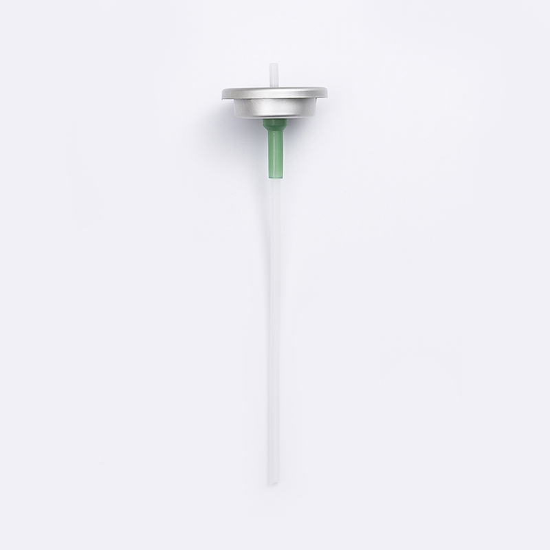
Typical precision aerosol spray nozzle – the interface between quantitative valve and application environment.
Portable Gas Stove Valve Systems: Precision in Miniature
Unlike liquid dispensing, gas stove valve applications require precise control of flammable gas flow rates while ensuring absolute shut-off integrity. The gas stove valve for portable stoves integrates a metering orifice, spindle adjustment, and safety thermocouple bypass. Systems designed for camping and emergency use must function after prolonged storage in temperature extremes (-20°C to 50°C) and resist clogging from oily residues.
A portable gas stove valve system typically includes:
- Inlet filter (screen mesh 50–100 μm)
- Needle valve for fine flow adjustment (0.5–3.0 LPM propane equivalent)
- Pressure regulator stage (nominal outlet 2.8 kPa for butane cartridges)
- Self-closing mechanism triggered by flame failure (thermoelectric or bimetal)
Performance metrics from a comparative study of 8 portable stove valve systems (non-branded) revealed that valves with hardened stainless steel needle tips maintained consistent gas output within ±3% after 5,000 actuations, while brass-needle designs degraded to ±15% drift. The gas stove valve design also influences ignition reliability: a 0.8 mm diameter orifice paired with a 30° conical needle yields optimal fuel-air mixing, reducing ignition failure rate from 8% to 1.2% in wind conditions up to 10 km/h.
Design note: Portable gas stove valve systems benefit from a soft-start feature – a secondary bypass hole that limits initial gas surge – reducing flare-ups by up to 70% during cold starts.
Synergy Between Valves and Nozzles in Precision Dispensing
The most sophisticated valve cannot achieve application success without a matched nozzle. System optimization requires simultaneous selection of one inch quantitative valve parameters and nozzle geometry. For example, a high-viscosity fluid (500 cP) needs a larger valve stem orifice (≥1.0 mm) and an L series nozzle with an expanded swirl chamber to avoid jetting. Conversely, low-viscosity solvents (<10 cP) work with small orifices but require careful nozzle material selection (PTFE or PEEK to prevent swelling).
Field data from an industrial lubricant line showed that replacing generic nozzles with l series nozzle designed for the specific quantitative valve increased dose accuracy from ±4.5% to ±1.8% without changing the valve itself. The improvement came from matching the nozzle’s internal backpressure to the valve’s spring closing force, ensuring complete chamber evacuation each cycle.
For fire extinguisher systems, the combination of a one inch fire extinguisher valve with a converging-diverging nozzle reduces discharge time by 18% for the same agent mass, due to improved pressure recovery and reduced turbulence. This synergy is critical for meeting UL rating requirements (e.g., 2A:10B:C).
Technical Selection Criteria for Industrial Applications
When specifying precision dispensing components, consider these five parameters with industry benchmarks:
- Flow coefficient (Cv) – For water at 25°C, target Cv = 0.02–0.15 for metered valves; 0.2–0.8 for continuous fire valves.
- Actuation cycle life – Minimum 50,000 cycles for aerosol valves; 5,000 for gas stove valves (ISO 23551).
- Media compatibility – Use elastomer compatibility chart (e.g., EPDM for brake fluids, FKM for hydrocarbon propellants).
- Operating pressure range – Quantitative valves: 100–800 kPa; fire extinguisher valves: up to 2500 kPa.
- Spray quality requirement – Measured as % of droplets within target size range (e.g., 90% of volume between 50–150 μm).
Manufacturers typically provide performance curves for each valve-nozzle combination. When data is unavailable, a simple bench test using high-speed imaging and gravimetric measurement can characterize metering repeatability and spray symmetry.
Frequently Asked Questions (FAQ)
Q1: What is the difference between a one inch quantitative valve and a standard continuous-flow aerosol valve?
A standard continuous-flow valve releases product as long as the actuator is pressed, while a one inch quantitative valve traps a fixed volume in a metering chamber before each discharge. This chamber ensures repeatable dose regardless of how long or hard the user presses, making it essential for pharmaceutical and high-precision industrial sprays.
Q2: Can I use an L series nozzle with any one inch fire extinguisher valve?
Not directly. Fire extinguisher valves typically have outlet threads or bayonet mounts designed for specific nozzle types (often with larger orifices to handle dry chemical or CO2). L series nozzles are optimized for liquid quantitative valves. Adapting one would require a custom coupler and pressure recalibration. Always check the manufacturer’s compatibility table.
Q3: How often should a portable gas stove valve system be serviced?
For residential camping stoves, inspect the gas stove valve annually for leakage (using soapy water) and after every 50 hours of use. Commercial or daily-use systems require valve replacement every 2 years or 500 hours, whichever comes first, due to seat wear. The thermocouple safety element should be tested monthly.
Q4: What spray pattern does an LE series nozzle produce compared to the standard L series?
The LE series nozzle typically produces a narrow solid stream (5°–15° spread) for deep cavity penetration or a flat fan pattern (up to 60°) with elongated tip orientation. The standard L series produces hollow or full cones (30°–110°) for broad coverage. LE sacrifices coverage for precision placement and reduced overspray.
Q5: Are there special materials for metered dose aerosol valves handling aggressive solvents?
Yes. For aggressive solvents like methylene chloride, acetone, or MEK, use one inch quantitative valve components made of PTFE or POM copolymer stems, Kalrez or FKM seals, and 316 stainless steel springs. Standard Buna-N gaskets swell and fail within 100 cycles in such environments.


